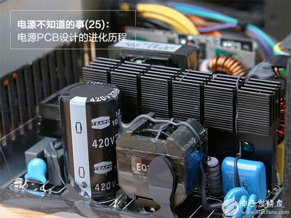
The first general-purpose computer was born in the United States in 1946. It covers an area of ​​170 square meters, and today our mainframe can even be as small as a USB flash drive. As a part of the mainframe, PC power supplies are constantly evolving. Today, I will briefly talk about the main evolutionary route of the internal circuit design of the PC power supply.
Review the power supply PCB structure
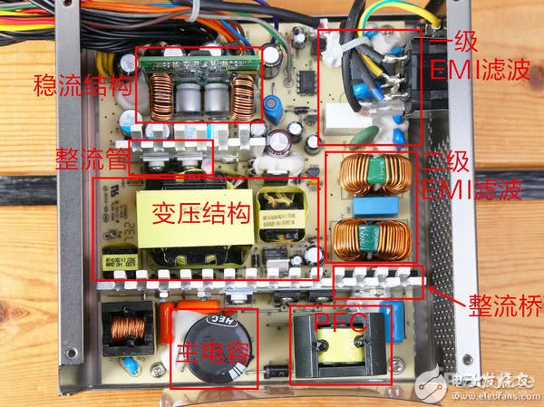
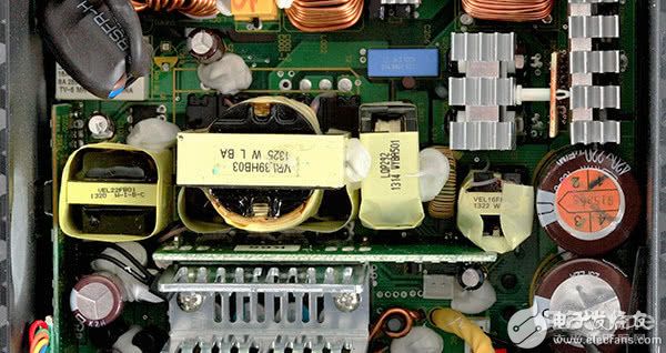
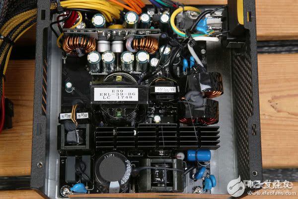
Before talking about the evolution of the PCB, let's first review the PCB structure of the power supply.
EMI filtering
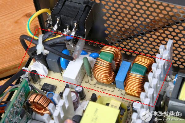
The role of the EMI filtering system in the power supply is to filter out the impurities in the mains, so that the input current is more pure and will not interfere with the operation of the hardware. Generally speaking, a normal-priced power supply will have one or two EMI filtering. Some power supplies put the first-level EMI filter on the input power pins, while the power supply in the above figure uses it on the PCB board.
Rectifier bridge
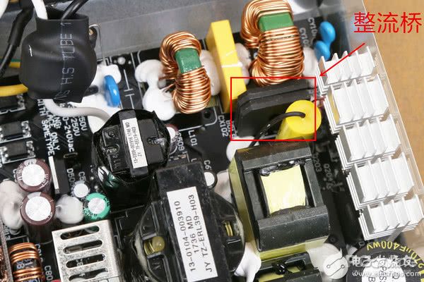
The current enters the PFC after filtering, and first passes through the rectifier bridge, which converts alternating current into direct current. Generally speaking, the rectifier bridge will generate a lot of heat when it is working. A well-designed power supply will lock the rectifier bridge on the heat sink. It is unreasonable to design two rectifier bridges directly on the PCB board like the Patriot Gaming 500. .
PFC
The current from the rectifier bridge enters the PFC. PFC is the abbreviation of Power Factor Correction, which translates to power factor correction. The alternating current is wavy, and the power supply using PFC can use not only the electric energy near the peaks and valleys, but also improve the utilization rate.
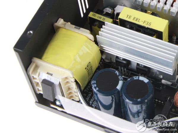
Main capacitor
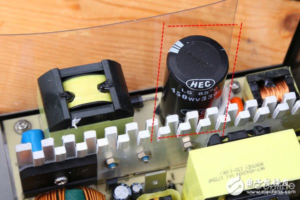
The role of the main capacitor (PFC capacitor) in the power supply: one is to filter, and the other is to store power to ensure that there is a certain amount of power to support the computer hardware to respond when the power is suddenly cut off.
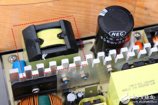
Transformer system
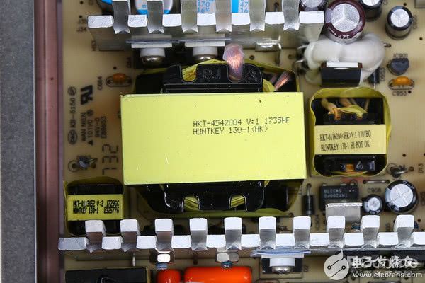
Next is the transformer system, which is generally divided into large and small transformers to step down the mains power to suit the host. The larger one in the picture is the main transformer.
Rectification, voltage stabilization, filtering
The rectifier tube is locked on the metal sheet
The current from the transformer will change from a rectification to a direct current, and then it can be output to the hardware of the computer after it is stabilized and filtered.
The evolution of power PCB structures
After reviewing the general structure of the power supply PCB, the next step is today's topic. This time I mainly talk about the evolution of PFC, voltage transformation system, rectification and voltage stabilization system on the power supply PCB.
PFC changes
A long time ago, PC power supply did not have a PFC structure. After the mains input was filtered by a diode rectifier capacitor, it could only use the energy near the trough and the peak trough of the wavy alternating current, and there would be no current input at other times in a cycle. , The utilization rate is quite low. The unused electric energy is not included in the electricity bill, so we will not cause any waste. On the contrary, the national power grid will waste electrical energy. The 3C certification of PCs in my country is that the power supply must have a PFC structure.
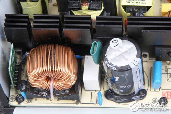
Passive PFC on the left side of the capacitor
PFC is divided into active PFC and passive PFC. Passive PFC is a large inductance coil, its power correction factor can only go up to 0.8, and the input voltage range cannot be too wide. However, the advantage of this structure is its low cost, which can be seen in many low-end power supplies.
There are control ICs and capacitors on the left and right of the inductor
In order to improve the utilization rate and expand the input voltage range, many power supplies have abandoned passive PFC and adopted active PFC. Active PFC is composed of inductor coil, filter capacitor, switch tube and control IC. Its power correction factor can easily reach more than 99%, and the input voltage range can also reach 90-240V, but the cost has also increased a lot. Evolving from passive PFC to active PFC, the reduction of power source waste is indeed a good thing.
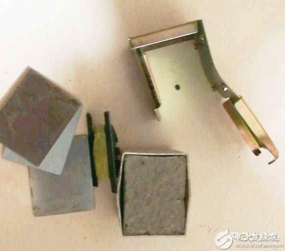
Cement PFC of Taobao's well-known brand "Jebo"
However, some black-hearted merchants actually use "cement PFC" for the power supply sold, and there is only one piece of cement in this fake PFC. This kind of power supply is quite dangerous to use. When buying a power supply, you should pay attention to the priority of using the active PFC power supply. If you want to buy a low-power power supply, you can buy a passive PFC power supply.
Changes in transformer structure
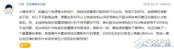
Speaking of the variable pressure structure, one thing must be mentioned: in an article by the master of smell, a netizen mistakenly regarded LLC as an old-fashioned half bridge and blatantly accused me. What is even more ridiculous is that there are still many netizens who point to it. Like agree. Of course, he is not to blame. The two structures are very similar at first glance. I hope you can tell the difference after reading this article and stop making such jokes.
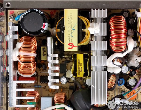
One large and two small transformers are similar in structure to LLC
Let me talk about the old-fashioned half-bridge. Its structure is very obvious. There are one large, two small and three transformers in the transformation system. Because this is an age-old power supply structure, its conversion efficiency is not high, and the top is less than 80%. But its cost is quite low, and it usually appears on low-cost and low-power power supplies. This kind of structure is generally matched with passive PFC to minimize the cost, but now there are very few power supplies with this structure. (It’s too old to find clear material)
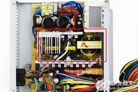
Large and small transformers located in the middle
At the beginning of the 21st century, another variable pressure structure began to emerge: the forward structure. Depending on the number of switching tubes, there are single-tube forward and double-tube forward structures. The biggest feature of this structure is that there are two transformers, one large and one small, in the transformation system. The two-tube forward structure has more switch tubes, and its performance is much stronger than that of the single-tube forward structure. Therefore, there are few power supplies with a single-tube forward structure. Compared with the old-fashioned half-bridge, the power conversion rate of the forward structure can be greatly improved, and it can reach the silver medal standard, but it is difficult to reach the gold medal standard.
Here is an extended version of the structure: the active clamp forward structure, which is a structure created by FSP. It can achieve the power conversion rate above the gold standard, but insufficient materials will cause the output ripple to be too large, so the corresponding cost is also increased a lot. Due to the low penetration rate of this structure, I will not introduce more.
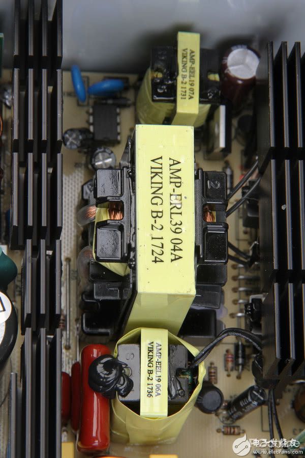
In recent years, a new type of structure called LLC has emerged. As mentioned above, this structure is similar to the old-fashioned half-bridge, with one large, two small and three transformers. In fact, there is a very simple way to distinguish, the conversion rate of the old half-bridge power supply is extremely low, and the conversion rate of the LLC power supply can easily reach the gold standard. We only need to distinguish between two different structures by the power conversion rate. LLC is divided into LLC half bridge and LLC full bridge. Generally speaking, the power conversion rate of this structure can meet the platinum standard. Compared with the two-tube forward structure, it has lower cost and weaker dynamic performance. The defect can be compensated by adding capacitance by brainless stacking. The most popular power supply structure at present. However, the performance of LLC structure is inferior to that of two-tube forward excitation for power supply below 400W.
Compared with the LLC half bridge, the LLC full bridge has a more complicated process, but its power and conversion rate are improved, and the cost will increase accordingly. We can see this structure on the high-power platinum standard power supply.
The evolution of rectifiers
Next, let’s talk about the changes in the rectifiers. In fact, the rectifiers have changed little. Most of the previous power supplies used multiple Schottky tubes for rectification, but now more and more manufacturers use MOS tubes instead of Schottky tubes for synchronous rectification. The use of MOS tubes can further improve the power conversion rate, and the power supply above the gold standard can basically see this design.
The regulated output structure is also optimized
Finally, let's talk about the regulated output part. Our common power supply will adopt single-channel magnetic amplification, dual-channel magnetic amplification or DC-DC structure. This structure will affect the output voltage offset of +12V, +5V and +3.3V. DC-DC has the strongest control performance, followed by dual-channel magnetic amplification, and the worst structure is single-channel magnetic amplification. The differences between these different structures are also quite recognizable.
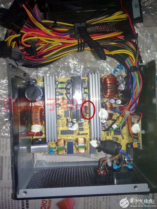
Single-channel magnetic amplification, separates +3.3V into one output. Its characteristic is that there is a small coil near the main transformer. And +12V and +5V are controlled by PWM chip. Therefore, the +12V high load will greatly affect the +5V output voltage. In the position of the steady current structure, there will be two coils to stabilize the current for +12V and +5V respectively.

Double-circuit magnetic amplification, separate +5V and +3.3V. The feature of this structure is that there will be two small coils near the main transformer, and there will be three large coils in the position of the steady current structure corresponding to +12V, +5V and +3.3V. Because +5V and +3.3V are independent, the impact on the other two output voltages will be reduced when +12V is high load. This is a structure evolved from single-channel magnetic amplification, which solves some of the defects in the use of single-channel magnetic amplification.
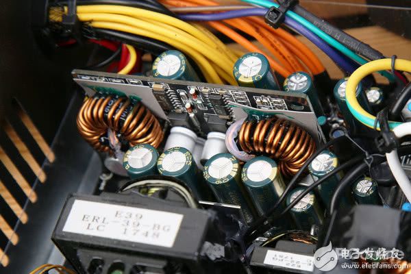
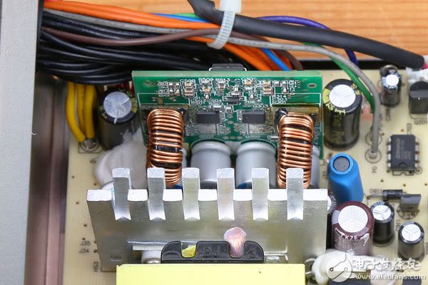
Although the dual-channel magnetic amplification structure can control the influence of +12V on the voltages of +5V and +3.3V, it cannot completely solve the problem. Therefore, a new type of steady current structure is available: DC-DC structure. Simply put, this structure is to take power from +12V and directly step down to +5V and +3.3V and then output, so the rated power of +12V can be increased without limitation. This kind of structure is the easiest to distinguish, there will be a vertical PCB at the position of the steady flow structure with two coils on it.
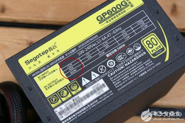
Even we can distinguish whether a power supply is a DC-DC structure without disassembling the inside of the power supply. We can observe the nameplate of the power supply. If the +12V maximum power of the power supply is very close to the rated power of the power supply, the power supply adopts a DC-DC structure. DC-DC is also gradually replacing dual-channel magnetic amplification as the standard design for high-wattage power supplies.
end
Over time, the structural design of the power supply is constantly changing. From the old-fashioned half bridge long ago to the forward structure and then to the current LLC structure, and even active clamp or phase-shifted full bridge structures, they are all developing in the direction of high conversion rates. The voltage stabilization structure has evolved from single-channel magnetic amplification to dual-channel magnetic amplification to the current popular DC-DC structure, aiming to evolve with a more stable voltage output. Many netizens will say: "A power supply I bought a long time ago can still be used now", "Isn't the cheap power supply working well". In fact, when the power of your computer is not high, the power supply with poor configuration can barely support the operation of the computer. However, cheap power supplies have a lot of influence on the power supply of computers.
At present, most power supplies use at least a dual-tube forward structure, while power supplies with high conversion rates use LLC structure. Of course, we must pay attention to the price of power supplies that use LLC half-bridges. The power supply must not be too cheap, because the power supply of this structure must pass a certain level. Capacitors of quantity and quality can support performance. The voltage stabilization structure is related to the voltage stability of the power supply output to the computer. When purchasing a power supply below 400W, we can purchase a power supply with a single-channel magnetic amplification structure. However, it is better to buy a dual-circuit magnetic amplifier or DC-DC structure power supply. Fortunately, many newly designed gold power supplies will adopt the more advanced structure of LLC plus DC-DC. I believe that after reading this article, everyone has a better understanding of power supply structure and development.
everyone enjoys luck , https://www.eeluckwatch.com