For the long-distance bus "three super" (overloading on the road, overtime, speeding) and the passenger car overload caused by private parking at the abnormal stop, the video surveillance equipment on the market is difficult to promote due to its large size and high cost. It is based on embedded problems in applications such as medium-sized vehicles, integrated USB camera low cost, USB storage media faster than SD (Secure Digital Memory Card) storage, and support for larger capacity. Dual uSB interface car video storage solution for Linux and S3C2440 platforms. This program mainly uses the single-chip discriminating module to collect the movement state information during the running of the vehicle (whether it is overspeed, there is sudden braking, midway stop timeout, etc.), and combined with the opening and closing of the door when the vehicle speed is zero, the long-distance bus is overloaded at the abnormal stop. Active video surveillance is carried out to facilitate future accountability and identification, and to provide assistance for the management of the monitoring center.
This article refers to the address: http://
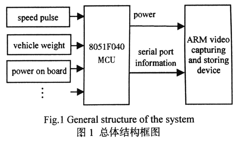
1 System overall structure design In order to facilitate system expansion, this paper divides it into two parts: single-chip discriminating module and video acquisition and storage module. The MCU discriminating module adopts the C8051F040 processor and uses its sufficient interface resources to make judgments on whether the vehicle is overspeed, emergency stop, overload, etc. The module completes the conditioning of the force sensor signal and the vehicle speed pulse signal for processing by the single chip microcomputer and communicating with the storage module. The measurement cycle method is used to measure the output pulse period of the vehicle gearbox, and then information such as vehicle speed and acceleration can be obtained. The measurement results of the force sensor are used to provide a judgment basis for determining whether the vehicle is overspeed, emergency stop, overload, and the like. The MCU encodes the above situation, and sends different information codes to the ARM video storage module through the serial port for different storage strategies. The overall structure of the system is shown in Figure 1.
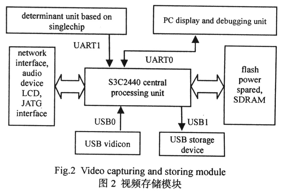
The video storage module determines the subsequent behavior according to the serial port information sent by the single chip microcomputer, such as whether to store, store time, storage location, and the like. The module hardware platform design is shown in Figure 2: The central processor selects the Samsung ARM9 architecture S3C2440 processor (can work stably at 400 MHz to ensure smooth acquisition and storage process); 64 MSDRAM memory and 64 MBFLASH are selected as system program storage devices. Interface resources include: 2 USB ports (all configured in HOST mode), 100 M Ethernet ports, 2 serial ports, and audio ports.
2 S3C2440 video acquisition and storage module The whole module is mainly powered by the single-chip system under normal conditions. In addition, an independent DC power supply unit is connected to prevent the vehicle from being turned off and in the event of a traffic accident, which affects the system operation. This module mainly completes the event-based storage function of the video. The judgment function is provided by the single-chip module, and the time-division multiplexing trigger function is provided according to the serial port real-time scanning characteristic. The modules are highly independent and suitable for porting to other occasions for promotion.
2.1 USB hardware connection and Linux kernel configuration modification
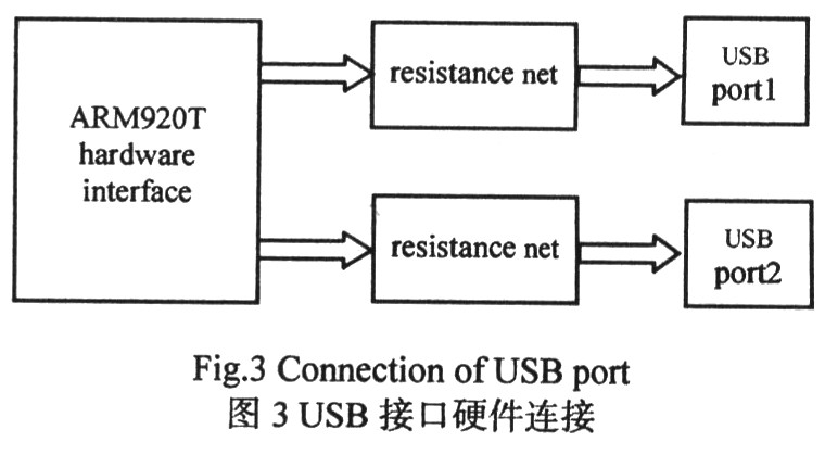
2.1.1 USB hardware connection Samsung S3C2440 chip has 2 channels of HOST USB: DP[1:0] and DN[1:0] ports, one channel DIVICE PDN0, PDP0 port, DP1, DN1 interface with PDP0, PDN0 respectively Multiplexing, with different functions depending on the relevant register configuration. In this topic, it is configured as a 2-way HOST, one connected to a USB camera, and the other connected to a USB interface storage device (can be a USB flash drive or a USB mobile hard disk). This article does not use the chip's own SD card interface for storage mainly because of the following considerations:
a) Speed: The data transmission speed of the ordinary SD card is about 2 MB/s; the data transmission speed of the high-speed SD card is about 10 MB/s; and the speed of the SD data transmission is about 20 MB/s. Now the universal USB2.0 has a full-speed transfer rate of 480 Mbps (60 MB/s), which is 30 times faster than a normal SD card. Furthermore, the USB 3.0 standard has been introduced with speeds up to 5 Gbps and is backward compatible. USB has become synonymous with high speed and convenience. The selection of USB in this paper is also considered for its versatility and convenience.
b) Capacity bottleneck: the existing release of embedded Linux 2.4. The X core supports SD card standard mode capacity to a maximum of 2 G (excluding 2 G). To support larger capacity, a large number of SD card drivers need to be modified, and the protocol standard is introduced relatively late, newer. The embedded Linux 2.6.24 kernel can support 2 G capacity through the actual verification of the author, but the driver has to be modified in multiple ways, the subsequent upgrade is complicated, and the stability needs further verification.
In view of the above two points, the USB interface is used for video data acquisition and storage, and the hardware connection of the two USB interfaces is shown in FIG.
2.1.2 Linux Kernel Configuration Modifications Under Linux, all peripherals are treated as a special file called a device file. The device driver provides interface functions between the kernel and peripherals to complete initialization and release of the device, various operations on the device file, and interrupt handling. These interface functions shield the application from the details of the peripheral hardware, allowing the program to operate on the peripheral like a normal file. The sub-module Video4Linux in the Linux system registers the video device file with the virtual file system, providing a unified API for the video application. The video application can manipulate various video capture devices through standard system calls.
Taking into account the better promotion, the commonly used Zhongxing Micro 301 series zc0301pl chip camera is available on the market. This camera supports image capture in JPEG format. The menu options such as USB OV511 Camera support and Device Drivers are configured appropriately in the module. In addition, you need to modify the USB configuration file. This article selects the Linux 2.6.24 kernel. The main modified files are as follows:
Linux-2.6.24/driVers/usb/host/Kconfig, linux-2.6.24/drivers/usb/host/ohci-s3c2440. c and linux-2.6.24/drivers/usb/core/hub.c. This mainly involves setting the MISCCR register correctly. To modify ohci-s3c2440. For example, the c file needs to be added with some code: 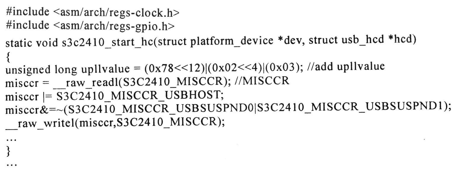
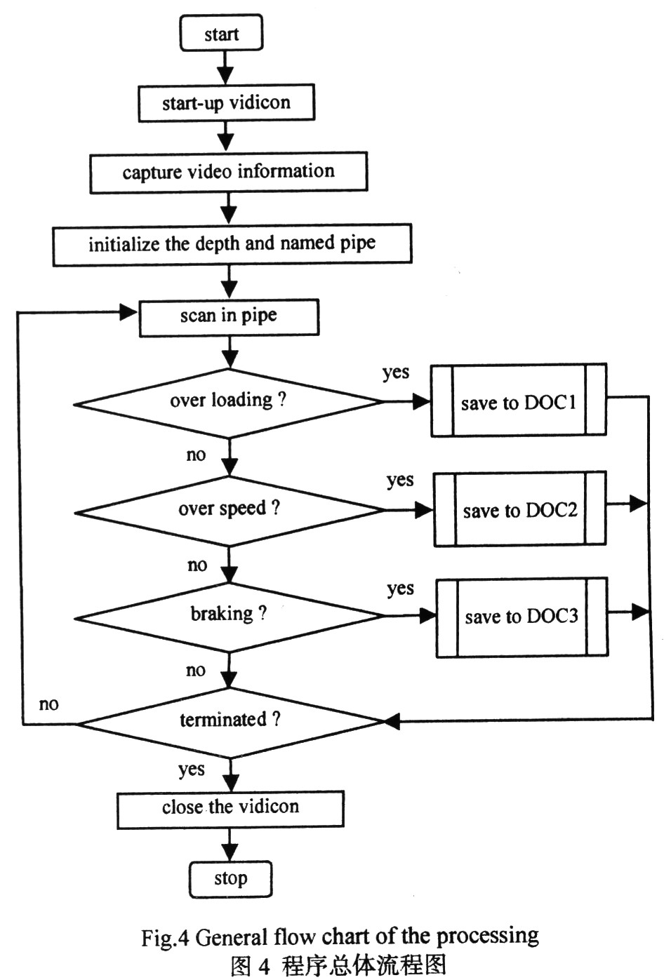
2.2 Video Capture Storage Program Design The Vide04Linux device driver only provides a series of functions for reading and writing functions of hardware devices at the system level. To implement storage, you need to write an application for video stream collection. In general, two processes are created: the process first scans the information received by the serial port, and sends the encoded information to the process 2 by reading the content of the named pipe; the process 2 makes a judgment according to the received code, and distinguishes various irregular driving behaviors. Set the timer for different durations to control the storage time and store the video classifications in different directories.
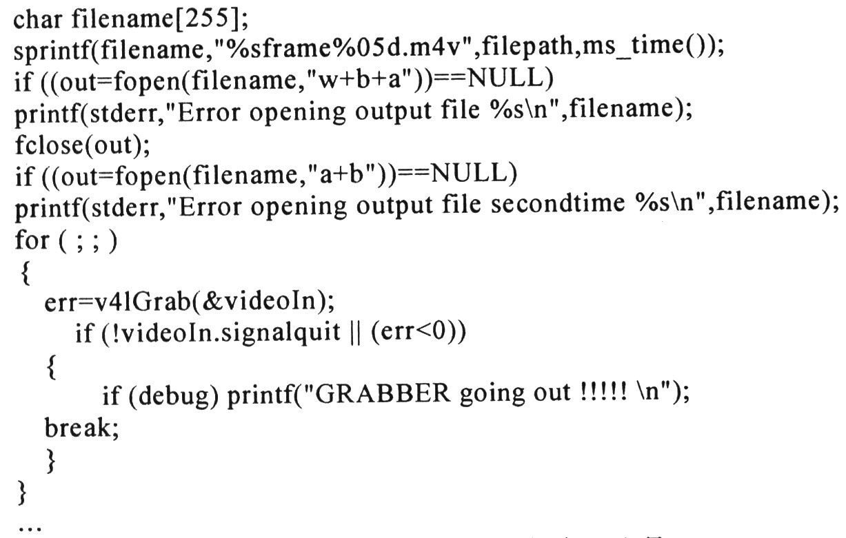
The Video4Linux device driver supports two ways to capture images: memory mapping mmap mode and direct read read mode. The mmap mode uses shared memory, and the data acquisition speed is fast, but this collection method requires camera hardware support. In combination with the camera used in this article, in the image acquisition process, the device file is directly read by the read mode, and the obtained frame data is saved into the buffer, and the data in the pFramebuffer is converted into the complete JPEG format by the convertframe() function. The data is stored in the ptframe, and then the fWrite() function is called to write the JPEG formatted data in the buffer to the specified file, thereby obtaining a JPEG format raw data block. Some of the procedures are as follows:
For storage control, this article uses the "named pipe" approach, which is a simple interprocess communication mechanism that supports reliable, one-way or two-way data communication between different processes on the same computer.
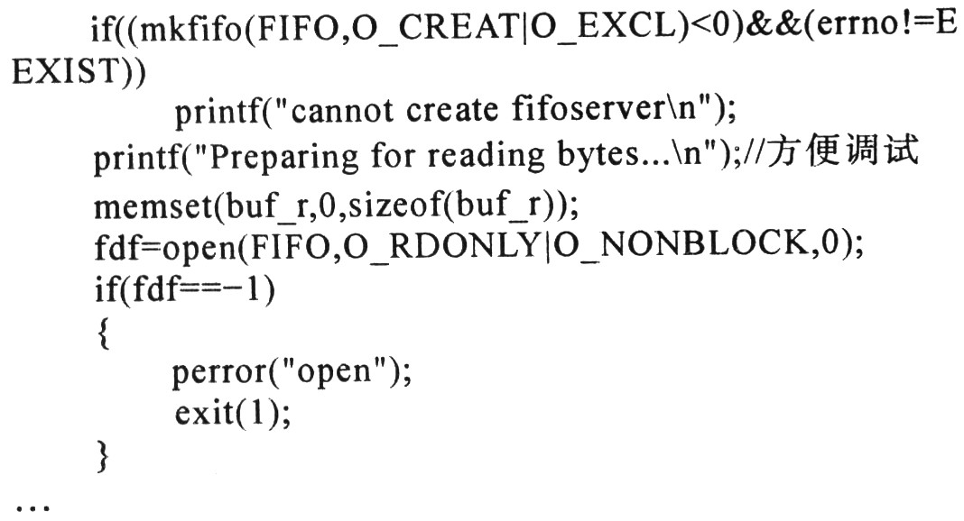
The named pipe is created by the video storage process using the function int mkfifo(constchar*pathname, mode_t mode), which is responsible for reading the control information received by the serial port scanning receiving process. Some of the procedures are as follows:
The overall flow chart of the program is shown in Figure 4.
3 Test Results The embedded kernel uses the newer version of Linux 2.6.24. After the configuration is successful, the compiled image file is downloaded to the target machine. The application executable file is generated by the cross-compiler arm-linux-gcc4.4.1 on the host machine, and can be run on the target machine after successful porting to the target machine. In this paper, the camera adopts Zhongxing Micro 301 series zc0301p1 chip, and the memory uses the U-storage storage star U disk with a capacity of 4 G.
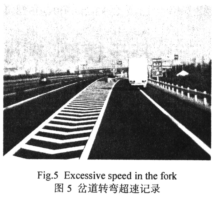
The video capture storage module separately establishes a DOCn (n=1, 2, ...) folder in the current directory location of the execution file according to the received different violation information, and saves the video information in the corresponding directory. FIG. 5 is a trigger picture generated by the driver at the turn of the ramp, and triggers a video in the video capture storage video. In addition, when the system is running, you can also set the length of recording time as needed to meet different requirements and memory capacity limits.
4 Conclusion In this system, the MCU module generates the trigger condition according to the operation result, and sends different coding information through the serial port to distinguish between overspeed, emergency braking and overload. The experimental results show that the whole system is easy to install, low in cost and stable and reliable in operation. In addition, by modifying the trigger condition of the single-chip module, it can be extended to intelligent monitoring based on event triggering in factories, banks and communities.
Car Battery Test Pen ,Car Battery Tester ,Digital Circuit Test ,Electric Circuit Test
YINTE TOOLS (NINGBO) CO., LTD , https://www.yinte-tools.com