The three authors of this article, Zhengyang, Haiyang, and Ali, are engineers from different companies. They combined the Agora SDK with the smart car to develop an innovative project for real-time video remote viewing through the smart car. This article will share their development experience in detail from project design to concrete realization. The trio also won the grand prize in the Agora RTC Hack Shanghai Station Programming Marathon that ended on July 1.
Ideas and Ideas
I have heard many times of activities such as "hackathons". A group of people from different places get together to form a team, conceive, develop, and make a prototype of a product within 48 hours. The three of us participated in this competition with the idea of ​​listening to others' ideas and focusing on participating. For what I want to do, there is only a general direction before the game:
The direction of the conception is based on the parts we are good at combining and splicing. This will have to talk about my two great teammates Haiyang and Ali; Haiyang is an embedded software engineer, car electronics, and write a driver to be a small driver. Ali is a back-end engineer with the ability to handle server-side and front-end pages.
As a result, the team has the capabilities of both embedded and cloud, and the direction of the technical concept is that the cloud empowers embedded. It is hoped that there is a small car, which can transmit back video images, and the video images can be transmitted to multiple users in real time. After the users are authorized, they can realize remote control of the car.
Scheme design and division of labor

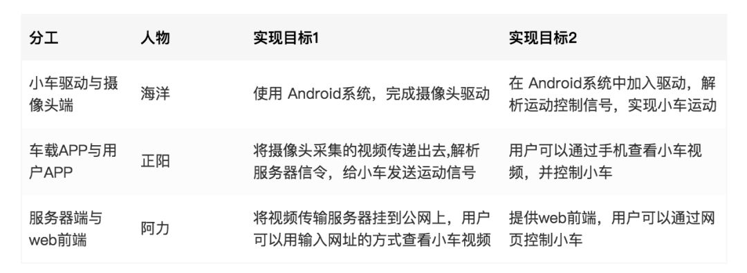
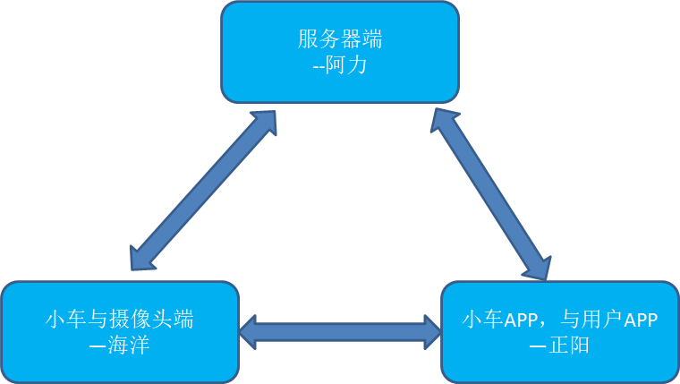
For this idea, the implementation architecture is shown in the figure above. Now that we have a basic architecture and a clear understanding of the functions we want to implement, the next step is the division of labor. Taking into account our respective strengths, the division of labor is as follows:
Start with hardware development
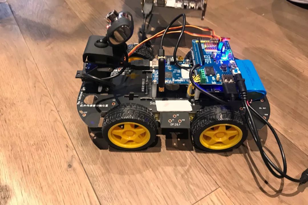
The trolley is driven by a 4-wheel servo motor, with a video capture module, a servo motor drive module, an STM32 control module and a camera pan/tilt module. The overall effect diagram after installation is as follows:
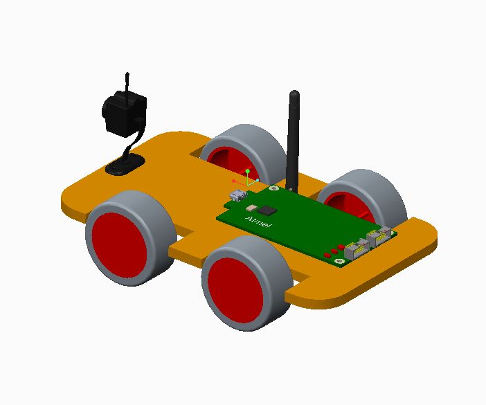
Picture: Effect picture
Before remotely controlling various actions of the car, the user needs to connect the car to the Internet via wifi. The user can control the trolley to move back and forth, or control the pan-tilt to adjust the camera direction through the upper computer (Android App or web front end).
The video capture module contains a Wi-Fi module, which can be connected to a wifi hotspot to provide a network basis for video transmission. An HDMI interface is also provided to connect to the display, which is convenient for users to debug. The camera is connected to the video capture module by USB. We use a driver-free Tianmin 6602 camera with a resolution of 640*480 and automatic focusing.
The STM32 control module uses the Arduino interface to connect with the servo motor drive module. The STM32 module is responsible for controlling the generation of the motor and pan/tilt signal, and the servo motor drive module directly drives the motor to work. Servo motor input voltage is 6~12V, DC drive.
working principle
The video capture module on the trolley uses a customized Android system to provide network connection, command forwarding, and video stream capture and transmission functions. When the host computer is connected to the car through remote service, the host computer can request the video information on the current car camera; at the same time, the video capture module also parses the control signal uploaded from the host computer into protocol data of the specified format and function, and passes The serial port is sent to the STM32 control module.
After receiving the relevant control signal, the STM32 control module on the trolley adjusts the duty cycle of the output pulse signal. After the output level is converted by the drive board, the servo motor or pan/tilt module directly controls the servo motor or pan/tilt module to make corresponding actions, thereby completing the host computer user The control function you want.
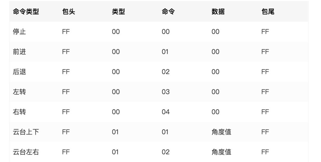
Control signal protocol
For simple car control, we only need to send control signals to the STM32 control module through the serial port. The simple control signal protocol is as follows:
Android SDK customization
development tools
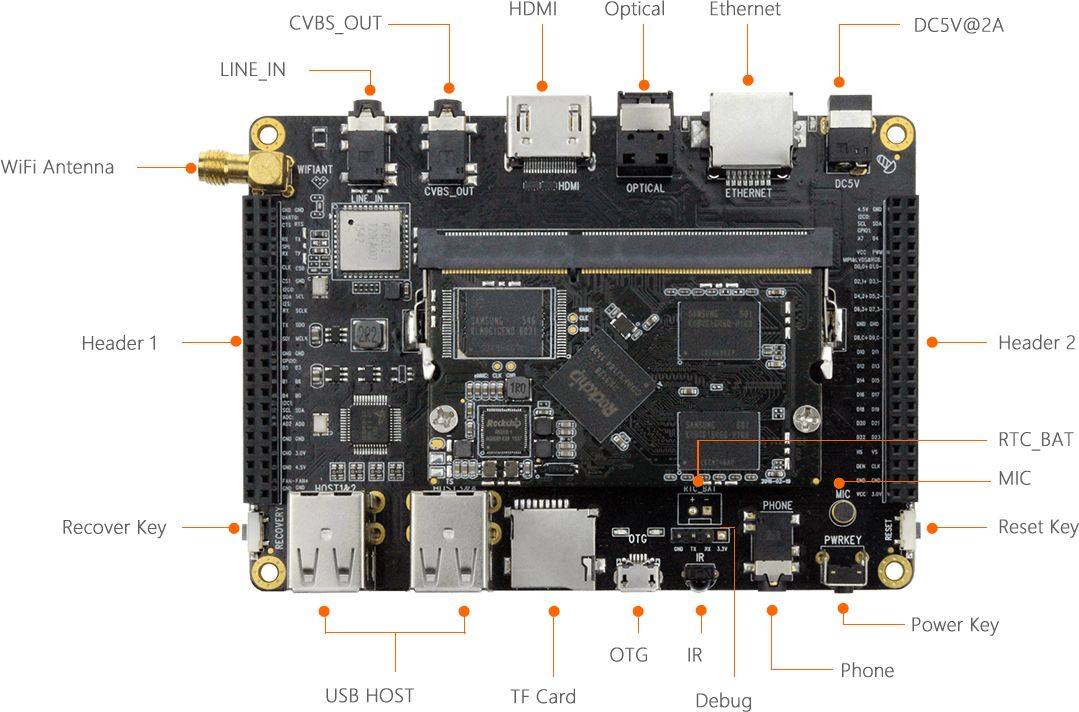
In order to achieve the real-time video and remote control function of the car we want, we need to use the video call SDK of the sound network and run it on the Android development board. For the development board, we chose Firefly’s RK3128 platform, using Cortex-A7 architecture quad-core 1.3GHz processor, Mali-400MP2 GPU, onboard Gigabit Ethernet port, 2.4GHz Wi-Fi and Bluetooth 4.0, supporting Android and Ubuntu dual system.
Custom serial port driver
In order to realize the control of RK3128 to the car, we need to realize the communication between RK3128 and STM32 control module through USB to serial port module. Therefore, we must first reconfigure the RK3128 kernel so that RK3128 supports USB to serial port driver.
First download the RK3128 Android SDK and verify the MD5 value of the file:
md5sum /path/to/fireprime_android5.1_git_20180510.tar.gzfce0e6d65549939167923260142b2c1e fireprime_android5.1_git_20180510.tar.gz
Unzip after confirmation:
mkdir -p ~/proj/fireprimecd ~/proj/fireprimetar xvf /path/to/fireprime_android5.1_git_20180510.tar.gzgit reset --hardgit remote add bitbucket https://bitbucket.org/T-Firefly/firenow-lollipop.gitgit pull bitbucket fireprime:fireprime
Configure and compile the kernel:
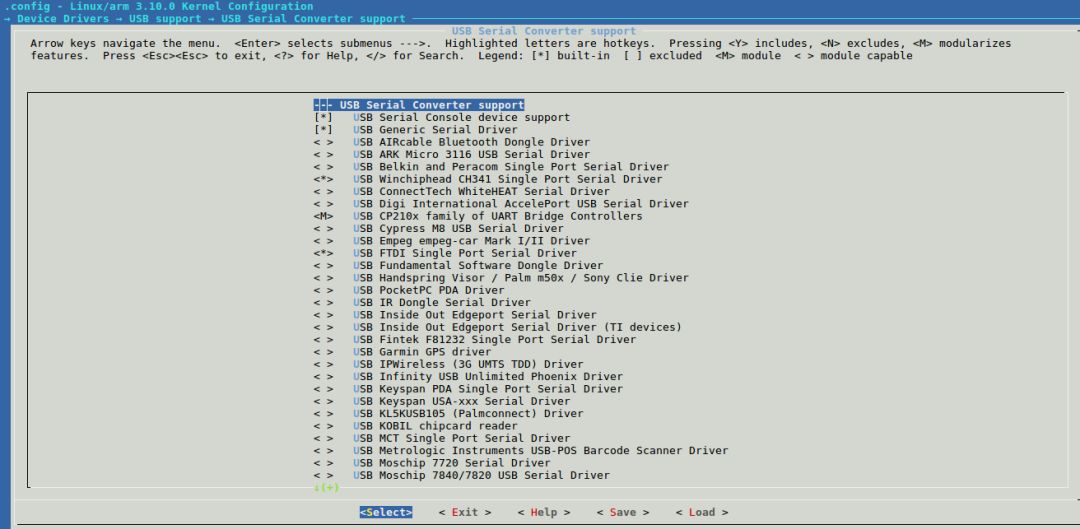
cd ~/proj/fireprime/kernelmake rk3128-fireprime_defconfigmake menuconfigmake -j8 rk3128-fireprime.img
In the make menuconfig step, you need to check Device Drivers —> USB support —> USB Serial Converyer support —> USB Serial Console device support / USB Generic Serial Driver, and check the commonly used serial tool devices such as CP210x / CH341 / FTDI / PL2303 .
Compile Android system:
cd ~/proj/fireprime. build.shmake -j8./mkimage.sh
Finally, after the compilation is completed, burn the partition image, and insert the USB to serial port tool to check whether the following log information appears in the system dmesg:
[2213.003173] usb 1-1.3: new full-speed USB device number 6 using rockchip_ehct[ 2213.113759] usb 1-1.3: New USB device found, idVendor=10c4, idProduct=ea60[ 2213.113839] usb 1-1.3: New USB device strings : Mfr=1, Product=2, SerialNumbe3[ 2213.113883] usb 1-1.3: Product: CP2102 USB to UART Bridge Controller[ 2213.113921] usb 1-1.3: Manufacturer: Silicon Labs[ 2213.113956] usb 1-1.3: SerialNumber: 0001[ 2213.120813] cp210x 1-1.3:1.0: cp210x converter detected[ 2213.209852] usb 1-1.3: reset full-speed USB device number 6 using rockchip_et[ 2213.320161] usb 1-1.3: cp210x converter now attached to ttyUSB0
When the serial port device is attached to ttyUSBx, it means that the serial port driver is successfully customized.
The above is the method of fully compiling the Android SDK. The Android system needs to be compiled, which is more time-consuming than just compiling the kernel. We can check the required serial port driver as M in the above make menuconfig, compile the driver into a .ko file through the method of make modules, and then automatically load the driver when the Android system is turned on:
First copy the .ko driver file to the Android file system
adb shellsumount -o remount ,rw /mkdir /moduleschmod 777 /moduleschown -R nobody:nobody /modulesexitexitadb push ./xxxx.ko /modules
Write startup and run script/data/serial.sh
#!/system/bin/shinsmod /modules/xxxx.komknod /dev/ttyUSB c 240 0
Modify init.rc and add your own script
service serial /system/bin/sh /data/serial.sh user root oneshot
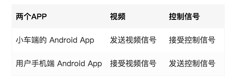
Realize video transmission on the App side
The part of video transmission and signaling transmission is realized through Agora SDK. As it involves the combination with the embedded development board, we mainly refer to the demos of the claw machine in various cases provided by Github. The structure diagram in the sample code is as follows:
The sample code has a video transmission part, and the control signaling needs to be completed by referring to the sound network signaling document.
Integration of Soundnet SDK
1. First apply for AppID
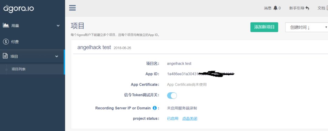
Add the following content in res/values/strings_config.xml in Android APP, configure agora_app_id
1a486ee31a30xxxxxxxxxx
2. Copy the .jar file to libs/
Because two parts of signaling and video transmission are used, two .jar files are needed, agora-rtc-sdk.jar and agora-sig-sdk.jar
3. Add armeabi-v7a and the .so file in src/main/jniLibs
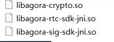
And make sure to have the following description in build.gradle:
dependencies {compile fileTree(dir:'libs', include: ['*.jar']) testCompile'junit:junit:4.12' compile'com.android.support:appcompat-v7:23.4.0'}
In this regard, using the sample code can smoothly start the video transmission function.
Use signaling to let App control the car
Realization of signaling
For the specific usage method of signaling, please refer to the reference in the document center of the official website of Shengwang. It will not be described in detail here. The main functions used are as follows:
// Initialize the signaling SDK m_agoraAPI = AgoraAPIOnlySignal.getInstance(context, appID); // Log in to the Agora signaling system m_agoraAPI.login2(appId, account, token, uid, deviceID, retry_time_in_s, retry_count)///////// /////Point-to-point test////////////// Send point-to-point message m_agoraAPI.messageInstantSend(account, uid, msg, msgID) // Set the callback of the message received by the peer (m_agoraAPI.onMessageInstantReceive (account, uid, msg){ //code there}/////////////channel test///////////////// join the channel m_agoraAPI.channelJoin (channelName)// Send channel message m_agoraAPI.messageChannelSend(channelName, msg, msgID)// Set the callback for receiving channel message m_agoraAPI.onMessageChannelReceive(channelID, account, uid, msg) {// code there}//// /////////////////////////////// Logout of Agora signaling system m_agoraAPI.logout()
Android App operation serial port
The Android App on the car side needs to send data through the serial port after receiving the signaling. So how to realize Android App operation serial port. Here are two scenarios:
It uses the architecture given by the Android system for processing. Android has a serial port demo code named SerialPort. Pay attention to two points here. The code here depends on the JNI tool and NDK. If it is not fully installed, there will be problems when using the project code. In addition, the serial port operation is not convenient to use the Android emulator for testing. For devices without a serial port, an error will be reported when the serial port is opened, and the program may exit and crash.
Choose to use the Android code to send shell commands to directly simulate the Linux shell control code. Example echo'aa'> /dev/ttyUSB0 sends aa to the serial port ttyUSB0. The advantage of this is that the code itself is simple, and the serial port directly calls the bottom layer.
For short-term implementation of functions, Option 2 is an easier way to implement. Here we need to pay great attention to the need to recompile the Android framework layer to give root permissions to the App
When the signaling analysis is completed and the serial port debugging is passed, the remote control of the car can be realized.
Finally: server-side deployment
In order to realize that users can conveniently view houses online in real time via mobile phones or computers, we need to connect to the Android App of the car through the Web terminal to obtain the video content transmitted in real time. In our vision, the user can remotely control the car, which can facilitate the user to understand all aspects of the house. In summary, we need to implement the following two functions:
With video connection function
With remote control function
Fortunately, through the services provided by Soundnet, we can easily build these two services. In this project, we use the video SDK of Shengwang to realize the video connection between the web page and the app of the car, and send messages through the signaling SDK to control the car’s forward and backward movement and the camera's swing up and down.
List the tools we use:
Soundnet video call Web SDK and documents are used to realize remote video interaction functions;
Soundnet signaling SDK and documents are used to realize remote control of smart cars;
Server, used to deploy static pages;
Realize video connection and send messages
First introduce the video and signaling SDK on the page. Then we first realize the video connection.
// Create an AgoraRTC instance and join the channel const client = AgoraRTC.CreateClient({mode:"interop"}) client.init(appId, function () {console.log("AgoraRTC client initialized"); client.join(channel_key, CHANNEL_NAME, null, function (uid) {console.log("User "+ uid +" join channel successfully") console.log(new Date().toLocaleTimeString()) // do something }}
Subscribe to the remote video stream and play.
let stream = AgoraRTC.creatStream(merge(defaultConfig.config))localStream.init(() =>{ client.on('stream-added', function (evt) {var stream = evt.stream; console.log(" New stream added: "+ stream.getId()); console.log("Subscribe ", stream); client.subscribe(stream, function (err) {console.log("Subscribe stream failed", err); }) ; }); client.on('stream-subscribed', function (evt) {var stream = evt.stream; console.log("Subscribe remote stream successfully: "+ stream.getId()); if ($(' div#video #agora_remote' + stream.getId()).length === 0) {$('div#video').append('
');} stream.play('agora_remote' + stream.getId()); });})Send information through the following methods.
// Create a signaling object const signal = Signal(appId)// Under the experimental conditions, don’t set token const token ='_no_need_token'// Login const session = signal.login(account, token)session.onLoginSuccess = (uid) => {//Send a message to the specified account signal.sendMessage(reciveAcount, message)}
After completing the above steps, set the same appId and token (if necessary) as the car terminal, set the corresponding parameters, we can remotely control the car and get the video
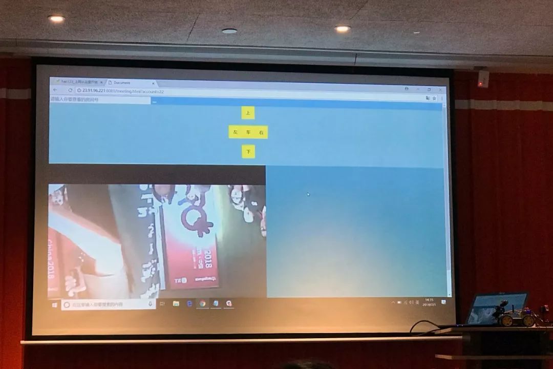
Picture: Live demonstration
Picture: 48-hour modified car
The products can provide various specifications of rectifier bridge devices according to customer requirements. The electrical properties, appearance, reliability, safety indicators and environmental protection indicators of the products all meet the relevant standards.
Planar Die Construction Sealed Glass Case Ideally Suited for Automated Insertion - 75V Nominal Zener Voltages
Case: MiniMELF, Glass Terminals: Solderable per MIL-STD-202, Method 208 Polarity: Cathode Band Approx. Weight: 0.05 grams= 25°C unless otherwise specified Symbol Pd VF RqJA Tj, TSTG Value to +175 Unit mW V K/W °C
Characteristic Forward Voltage = 200mA Thermal Resistance, Junction to Ambient Air (Note 2) Operating and Storage Temperature Range Notes:
1. Tested with Pulses, 20ms. 2. Valid provided that Electrodes are kept at Ambient Temperature.
1. Tested with pulses = 20 ms. 2. Valid provided that electrodes are kept at ambient temperature.
VZ, ZENER VOLTAGE (V) Fig. 1, Zener Current vs Zener Voltage
25 20 VZ, ZENER VOLTAGE (V) Fig. 8, Zener Current vs Zener Voltage
TA, AMBIENT TEMPERATURE (°C) Fig. 3, Power Dissipation vs Ambient Temperature
15 20 VZ, ZENER VOLTAGE (V) Fig. 4, Differential Zener Impedance
VZ, ZENER VOLTAGE (V) Fig. 5, Junction Capacitance vs Zener Voltage
MINI MELF,Smd mini melf,zener mini melf,mini melf package,mini melf resistor,mini melf diode,mini melf resistor datasheet
Changzhou Changyuan Electronic Co., Ltd. , https://www.cydiode.com