The charge pump application is essentially equivalent to a voltage doubler rectifier circuit in the circuit. In some places where high voltage and low current are required, a voltage doubler rectifier circuit composed of a charge pump is often used. The voltage doubler rectification means that a lower AC voltage can be used to "conform" a higher DC voltage with a rectifier diode and capacitor with lower withstand voltage. Charge pumps are generally divided into double voltage, triple voltage and multiple voltage charge pumps according to how many times the output voltage is the input voltage.
Voltage pump circuit diagramThe voltage pump circuit has a variety of structures, each with advantages and disadvantages. Common circuits are as follows:
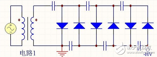


These three circuits are all 6 times voltage pump circuits, each with its own characteristics. We usually say that every 2 times is the first order, denoted by N, the above circuits are all 3 orders, that is, N=3. If you want the output voltage to be different in polarity, just reverse all the diodes.
Advantages and disadvantages of three circuit voltage pumps1, circuit 1
The advantage is that the voltage on each capacitor does not exceed twice the secondary peak voltage U of the transformer, ie 2U, so a capacitor with a lower withstand voltage can be used. The disadvantage is that the capacitor is in series discharge and the ripple is large.
2, circuit 2
The advantage is that the ripple is small, and the disadvantage is that the voltage withstand voltage of the capacitor is high, and as N increases, the voltage stress of the capacitor increases. The voltage of the last capacitor in the figure reaches 6U.
3, circuit 3
It is an improvement of circuit 1. The advantage is that the ripple is much smaller than that of circuit 1, and the voltage stress of the capacitor does not exceed 2U. The disadvantage is that the circuit is complicated.
How does the voltage pump circuit diagram work?The circuit 1 is taken as an example to illustrate the working principle:

When the secondary output of the transformer is up and down, the current flows as shown. The transformer charges energy to the three capacitors of the upper arm.
When the secondary output of the transformer is up-down, the current flows as shown. The upper arm capacitor is charged through the secondary arm of the transformer.

If there is no load, in steady state, except for the leftmost capacitor, the voltage on each of the other capacitors is 2U, so the total output voltage is 6U. In fact, due to the poor carrying capacity of the high-order voltage doubler rectifier circuit, the output of a small power will cause a large drop in the output voltage. Assuming that the output current is I, the capacity of each capacitor is the same, C, and the AC power frequency is f, then the voltage drops to:

The output voltage ripple is:

The diode used in the voltage doubler rectifier circuit should have a maximum reverse voltage greater than. A high-voltage silicon rectifier stack is available, and its series model is 2DL. For example, 2DL2/0.2 means that the highest reverse voltage is 2 kV and the average rectified current is 200 mA. The capacitor used in the voltage doubler rectifier circuit has a relatively small capacity and does not require an electrolytic capacitor. The capacitor's withstand voltage is greater than 1.5x, which is safe and reliable in use.
Function description
The socket is ordinary converter,with two output 5V2A power USB power supply at the same time,can be very convenient in use electrical appliances and recharge the equipment at the same time,such as digital products like Iphone Ipad,MP3,MP4 etc.The charge apply to full range of international AC output,no-load power consumption less than 0.3W,with short circuit,overload,over-voltage protection,can be convenient for your life and save more energy
Timer Control Time Adgustment
1.Press the power switch 1 time,the 1HOUR LED will light on.The Timer into ON mode,USB and control socket output ON .
2.Continuously press the power switch the LED light on,the Countdown mode and LED light on will cycle change from 1HR,2HR,4HR,6HR,8HR,10HR.
3.Choose you need countdown time mode,the mode LED will lighto on,start countdown until countdown time finish,the control output and USB change to OFF
4.Then the countdown is start,The Time indicate LED will from high to low auto change until Countdown finish off.
Failure analysis:
1.check whether the power supply connection is good
2.check whether the USB cable is loosen
Warning Note:
1.Use indoor and dry location ONLY
2.The load max does not exceed 15A 3600W
3.This product does not convert voltage please do not miss use DO NOT exceed the maximum loading of 3600 Watts 15A
4.Always have earth connection for safety reason
5.If in doubt please consult with a qualified electrician
USB countdown timer, USB countdown timer socket, USB timer, USB charger timer, USB timer socket
NINGBO COWELL ELECTRONICS & TECHNOLOGY CO., LTD , https://www.cowellsocket.com