When the system for evaluation is unique and complex, comprehensive verification and testing often requires some innovation.
While most of the testing and measurement work begins with evaluating components and boards, it often brings diverse, complex, and more difficult testing challenges to the final complete system. System testing often requires the development of highly specialized and unique configurations that require custom electronic and mechanical components. (Of course, almost all advanced systems related to rockets, manned/unmanned space travel, satellites, etc. fall into this category.)
This is the case with infrared (IR) sensors that are widely used to detect missile targets. But the question is how to test the performance of these high-resolution sensors and systems? The answer is “simpleâ€: only one IR scene projector is needed. In fact, these projectors must create images of high resolution that are meaningful and programmable so that images can be dynamically changed. To do this, it requires a special array of IR light-emitting diodes (LEDs).
Chip Design Systems (CDS), a US chip and prototype system architecture company, has overcome this problem. Chip Design Systems was founded in 2013 by Professor Fouad Kiamilev of the University of Delaware, and was spun off from the CVORG lab of the Department of Electronics and Computer Engineering. The company specializes in developing chips, packages, and hardware and software solutions for generating thermal scenes to test and correct infrared detector arrays.
Chip Design Systems has teamed up with the Air Force Research Laboratory and other universities to design a short-wave infrared LED projector to test these new sensors. The projector produces infrared scenes at unprecedented resolutions, twice the speed of the prior art, with much higher brightness, and the ability to program pixels separately.
The key to the program is an infrared LED array that uses a new method to shrink the read chip (RIIC). This architecture reduces chip size by subtly sharing transistors between adjacent pixels instead of using more sophisticated CMOS technology that is more complex and prone to defects. The 512 x 512 pixel scene projection system operates at 100 Hz and uses a medium wave (3 to 5 μm) superlattice LED array. These LEDs are flip-chip bonded to the read chip and display temperatures as high as 1,350 K when liquid nitrogen is cooled to 77K. The array subsystem uses custom drive electronics (Figure 1) and package and performs non-uniform correction (or NUCed).
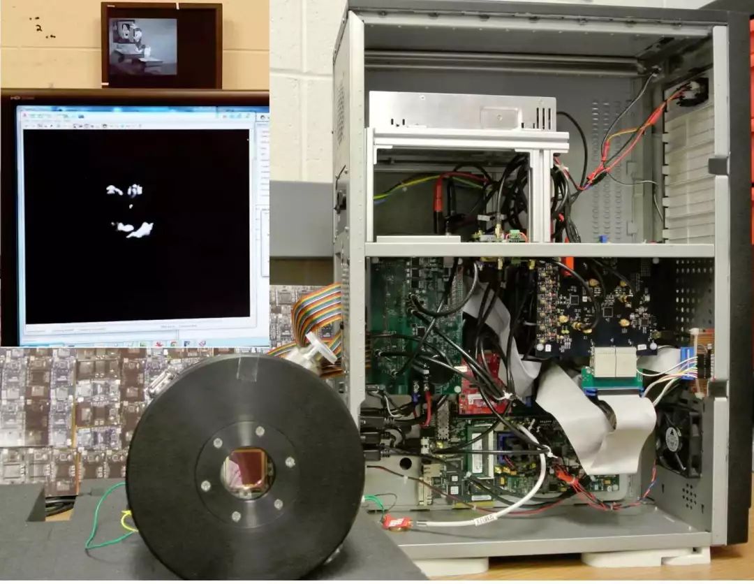
Figure 1: The drive electronics of a 512 x 512 pixel system uses an innovative topology (source: University of Delaware)
Of course, the complete system test is more complicated than this IR LED array; in addition to a considerable number of devices, more people need to invest and frustration. To date, approximately 30 graduate students (including masters and doctoral students) have participated in the development of this prototype system (Fig. 2), which has been successfully evaluated at Elgin Air Force Base, Florida, USA.
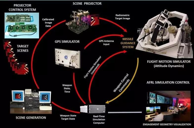
Figure 2: The diagram shows the technology developed by Chip Design Systems, the University of Delaware, and the University of Iowa, and how it can be used in the laboratory to evaluate infrared missiles in flight. :Air Force Research Laboratory)
Of course, component and board testing are the basic building blocks for system testing. But even fully functional and tested modules may not be able to complete tasks as they advance new areas. This is one of the obvious challenges of system testing. Not only do you have to configure and debug system test schedules, but you also need some independent, or even completely different, ways to verify that the test system provides valid results. Whether the problem is a basic correction or a larger error or misunderstanding, high-level advanced system testing can be well worthwhile and frustrating.
Have you ever had to develop a dedicated test tool for testing unique and never-behaved systems? What "surprise" have you encountered in the process? Successfully overcome the problem and still remember it clearly? Please share with us.
1.ANTENK FEMALE HEADER Series Receptacle Strips are a series of sockets offered in a multitude of sizes and profiles designed to satisfy most .100" pitch socket requirements. Available in Single, Dual and Triple row, they are offered in Straight, Right Angle, SMT, Bottom Entry and Pass Through PCB mounting styles. Each type has a specially designed contact system which uses a wiping mating action and produces a high normal force connection with gold, tin or selective gold plating. All are available with Standard or Hi-Temp Thermoplastic insulators. Our SMT offering is available with optional pick and place pads and tape & reel packaging.
2.Our products are widely used in electronic equipments,such as monitors ,electronic instruments,computer motherboards,program-controlled switchboards,LED,digital cameras,MP4 players,a variety of removable storage disks,cordless telephones,walkie-talkies,mobile phones,digital home appliances and electronic toys,high-speed train,aviation,communication station,Military and so on


2.54 Famale pin headers
SPECIFICATION
Current Rating: 3.0 Amp
Insulation Resistance: 1000M ohms min
Contact Resistance: 20M ohms max
Dielectric Withstanding: AC500V
Operating Temperature: -65°C to +125°C
Contact Material: Brass
Insulator Material: PBT,UL 94V-0 Black
Female Pin Headers,Pcb Female Connectors,Pin Connector Header,Oem Female Header
ShenZhen Antenk Electronics Co,Ltd , https://www.antenkwire.com