Cd4011 internal 4 sets of NAND gates, power supply is 14 positive, 7 negative, 123 feet are a group of NAND, 12 feet at the same time high level, 3 feet are low level, 12 feet other state 3 feet are high power Ping, the other three groups are inverters in the circuit, that is, 11 feet and 3 feet are opposite, 3 high 11 low, 3 low 11 high, 1 foot external light control, 2 feet for trigger delay, the process is probably such
Cd4011 pin diagram and pin function
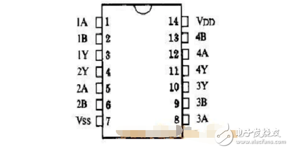
Pin function:
1A Data input 2A Data input 3A Data input 4A Data input 1B Data input 2B Data input 3B Data input 4B Data input VDD Power supply VSS Ground 1Y Data output 2Y Data output 3Y Data output 4Y Data output
CD4011 internal structure block diagram: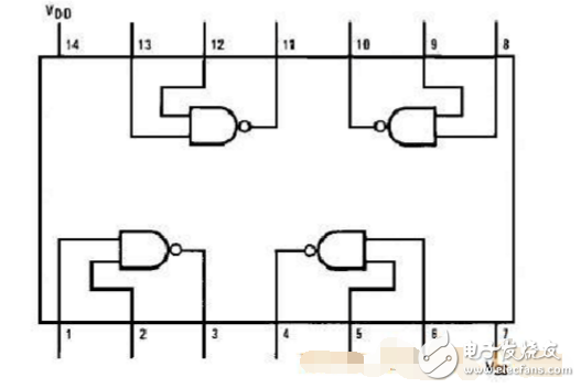
Interlock switch circuit
This circuit is used for switching the preamplifier source and equal loudness and flat switch control. With relay switching, audio signal routing can be arranged more reasonably. See below:
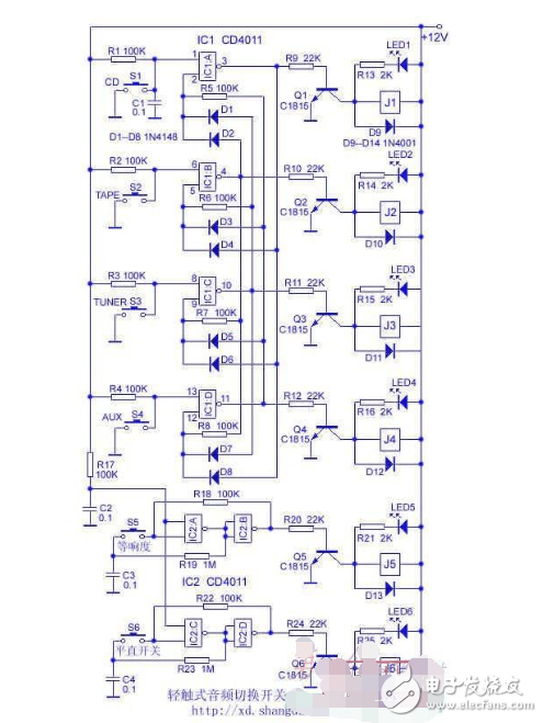
control. It can be known from the circuit principle that they are bistable circuits, and the operation principle of the equal loudness control is now taken as an example.
When the power is turned on, +12V charges the C2 through R17 to form a momentary low potential on the (1) and (8) pins of IC2A and IC2C, so that IC2B and IC2D output low level and are maintained by R18 and R22 respectively. J5 and J6 are not Pull-in, that is, the equal loudness and flat switch are placed in the "off" position. The high level of the IC2A output is charged to C3 through R19 until it is close to the supply voltage. If S5 is pressed, the high potential on C3 is applied to the (2) pin of IC2A to make IC2B output high level, Q5 is turned on, J5 is pulled, and the contact will be in the "on" position. At the same time, this high level sets the (2) pin of IC2A high through R18, and the high level is held after releasing S5. Since the output of IC2A is low, C3 discharges through R19 until it goes low. If you press S5 again, the (2) pin of IC2A is pulled low by C3, so that the IC2B output is flipped low and J5 is released. At the same time, due to the role of R18, even if S5 is released, the low level of IC2B output will be maintained. In addition, since IC2A outputs a high level, R19 charges C3 until it is close to the power supply voltage, ready for the next flip.
LED1 to LED6 are used for the indication of the status. S1 ~ S6 select 6 & TImes; 6mm tact switch. J1 ~ J6 is recommended to use DS2Y-S-DC12V small DC relay, which has two pairs of silver-plated contacts, the contact resistance is very small. The connection of the contacts is very simple. Replace the contacts of J1~J4 directly with the sound source switch in the original picture, and replace the J5 and J6 contacts with the equal loudness switch and the straight switch in the original picture. The circuit diagram is no longer given here. This circuit does not require high 12V power supply and does not need to be regulated.
The circuit does not need to be debugged, and the installation can be completed without checking the power.
Conductive slip rings are one of the most popular types of electrical connectors. They consist of an insulating sleeve enclosing two metal contacts, with a small gap between them. When current is applied to the ring, it creates resistance between the contacts, which can be used to form a continuous circuit. They can be used in a wide range of applications, such as medical equipment, robotics, aerospace systems, and more. The construction of a conductive slip ring typically consists of two rotors (or rings), with each one containing a number of stationary contacts. When the rings rotate, the contacts move past each other and create an electrical connection.
In today's increasingly electronic world, the need for efficient and reliable power transmission is more important than ever. That's why more and more businesses are turning to slip rings as a means of transmitting power in a variety of applications. Slip rings are electrical connectors that allow current to flow continuously through a rotating assembly, making them ideal for use in devices that require uninterrupted power transmission, such as motors, generators, and wind turbines.
Oubaibo is a leading manufacturer and supplier of conductive slip rings, slip ring power connectors, and other related products. With years of experience in the industry, our products are known for their quality and durability. We offer a wide range of products to meet the needs of our customers, including standard slip rings, high voltage slip rings, military-grade slip rings, and many others.

Conductive Slip Ring,Slip Ring Power Connector,Electrical Slip Ring Assembly,Slip Ring Design
Dongguan Oubaibo Technology Co., Ltd. , https://www.sliproubos.com