Need material
Two used optical drives
An Arduino UNO development board
Two A4988 stepper motor drive modules
A 12V2A power module
a 250mv laser head
An acrylic sheet
Several wires
Several screws
AB glue
2. Disassemble the optical drive
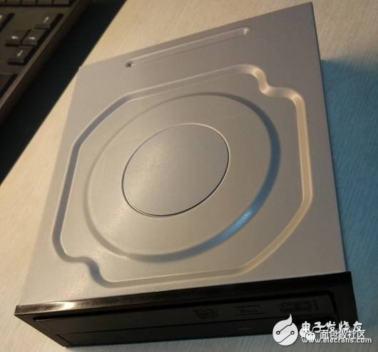
Since I have been doing micro laser engraving machine for almost half a month, some pictures were not taken at the time, so some pictures here are found online.
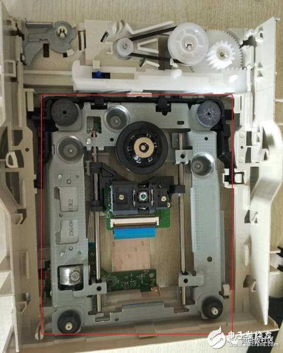
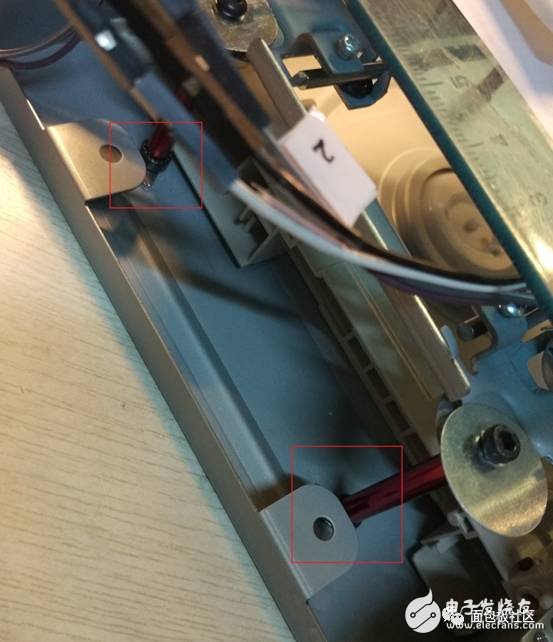
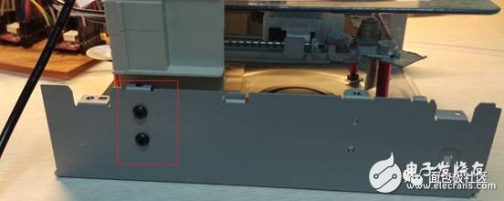
Note: After you remove it, don't throw the rest of the material. For example, strong magnets on both sides of the laser head, optical drive housings and plastic screws.

The red frame in the figure is the location of the powerful magnet.
3. Pull out the motor pins
Note: The motor pin sequence is messy.
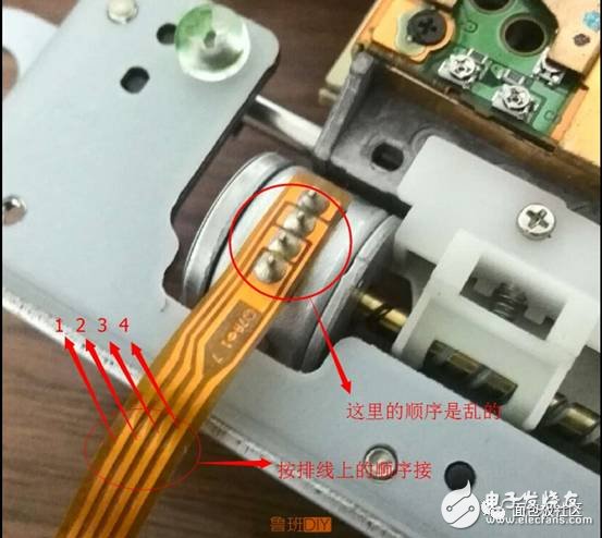
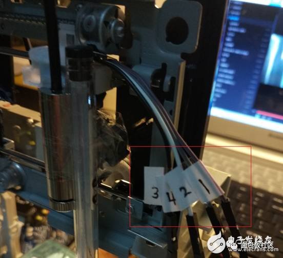
It is best to mark the pin order (shown in red in the figure).
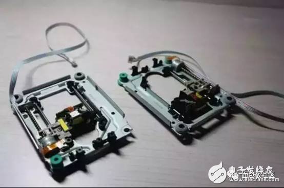
4. Fix the acrylic plate and add the column foot to the x-axis optical drive.

The one below is defined as the x- axis and the top is the y- axis.
Here , the plastic in the x- axis optical drive is cut into a flat surface, and the acrylic sheet is stuck with AB glue.

Give the four legs of the x- axis support and add screws to each leg.
You can put the x- axis drive here .
5. Fixed y-axis optical drive and bracket
First fix the laser head on the y- axis optical drive, and then fix the optical drive to the black plastic. Here when the screw is on (the place is too limited, so I only have two screws. Everyone has a gasket and try to add the gasket. I have limited material and can only use a small piece of gasket from the corner.), white plastic In some places, it will block the optical drive from moving up and down, and it is necessary to use force to remove obstacles. The reason why it should be fixed on the black plastic is because the material is used locally, and the material of the waste optical drive is used as much as possible. Secondly, because there is a motor behind the black plastic, the y- axis optical drive can move up and down, and can also hover freely to facilitate the adjustment of the focal length. And it can also be used for the second transformation (for example, the motor behind it can be made into z- axis, it can be stereoscopically engraved or 3D printed ^_^ ) ; the third is because the optical drive material itself is vertical and vertical, and it is more than the frame made by itself. Fishing is more stable.
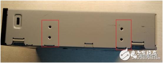
At this time, the y- axis optical drive, black plastic, and white plastic are integrated. Turn two holes on the left and right sides of the white plastic, the size is about the same as the two holes on the optical drive iron box, and then fix the screws. At this point the whole whole is very stable.
6. Combined xy-axis optical drive
Twist the screws under the x- axis drive to adjust the acrylic plate to the horizontal position.
Then put the x- axis drive under the y- axis drive and adjust the position to place the powerful magnet under the four legs. Don't underestimate these four powerful magnets, its suction is enough to make you can't get an x- axis drive in one hand . So the position is best fixed once.
Here, do you find that the waste optical drive is a treasure? ^_^
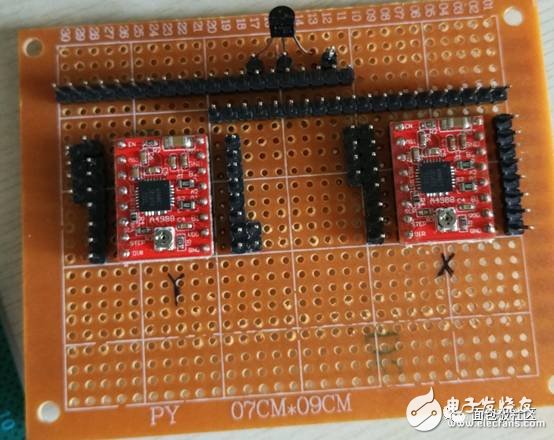
7. Refer to the circuit diagram connection
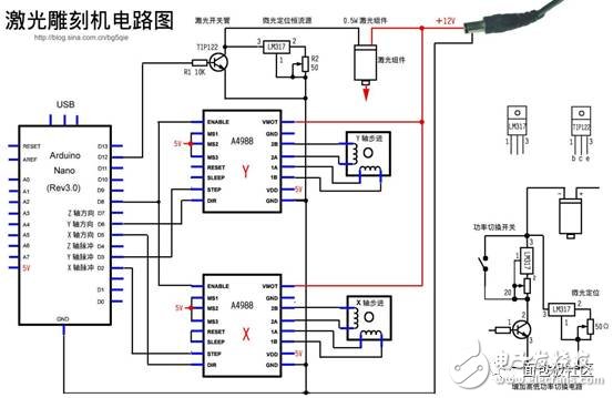
This picture is found online.
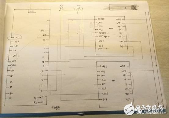
This is my own painting. Because it is not a student of electronics major, pure amateur, the circuit diagrams are all hand-painted.
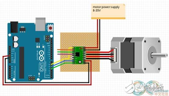
This is the connection method of the A4988, and the A3967 is also available online .
8. Power supply problem
There may be a big god here that power supply is not a problem, but I am amateur, and I have encountered some problems in the power supply problem. I want to share with you here.
First, the motor power use 12V2A, Arduino UNO boards and A4988 5V use electrically driven.
5V is easy to find, such as the phone charging head can output 5V .
12V electricity I borrowed from a friend who played the aircraft, just can output 12V2A charging head.
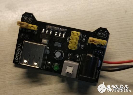
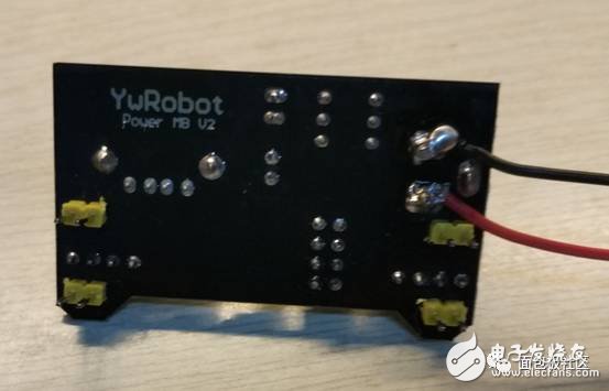
Transform the power module, insert the 12V charging head into the power module, use the meter to measure the positive and negative, the lead can be used! Very convenient, so 5V and 12V are on one module.
The way it is connected.
9. Software installation
1 Download the GRBL Controller , which is the control software for the laser engraving machine.
2 Download INKSCAPE , which is a vector graphics software that can be converted to Gcode files.
3 Download the GRBL firmware and download it to the Arduino .
The first icon software is for Arduino programming.
G code found online .
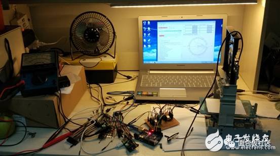
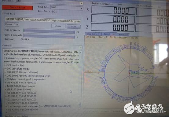
10. Debugging
First connect Arduino , put the code down and then turn on the power.
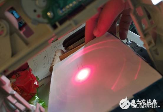
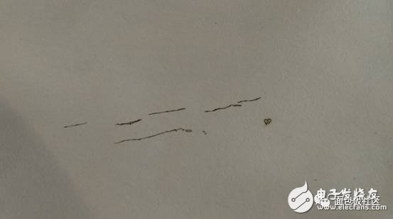
Here I don't have a good focus. I can only use the cardboard to burn a few thin lines and a small hole. I will use the pen instead of the laser directly later.
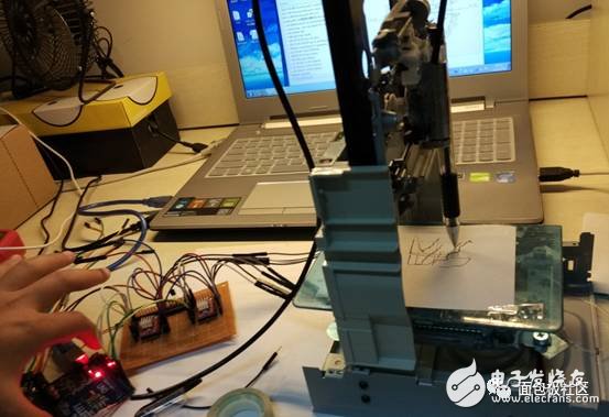
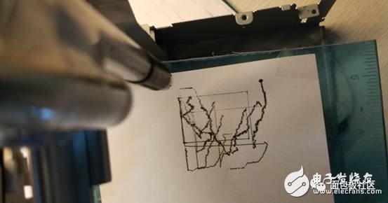
Since the range of the G code found on the Internet is larger than the range drawn by the micro laser, I drag it back to the boundary and finally draw it far worse. There is still more room for improvement in this work. I will share it with it and hope to help those who want to do it.
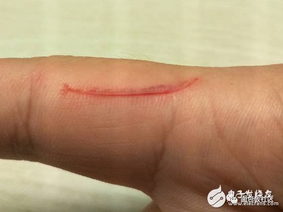
Finally, I hope everyone must be careful with tools.
We are a professional manufacturer in the cabling solutions supplies in Ningbo, we could offer the Patch Panel in 8-48 ports, cat5e, cat6 cat6a specification; Metal or plastic Cable Management with brush; the Keystone Jack in UTP and STP style; surface wall mount box in blank, cat5e cat6 or other mount box; the RJ45 Modular Plug in 8P8C, cat5e, cat6, cat7 basing on UTP and STP Style; 86 type, UK type, France, type, German type, USA type Face Plate in 1 port to 8 ports; Stripper and Crimping tool and tool kits, cable tester for RJ11 RJ12 RJ45, HDMI,USB connector; cabling solution accessories like as cable tie, Cabinet screw, LSA module frame, indoor and outdoor distribution box, fiber optical distribution box and patch panel.
We have more 6 staffs in QC team, and 4 staffs in technical division to keep the high quality of products and service to our customers.
CAT5E Patch Panel,STP Patch Panel,24 Ports Patch Panel,keystone patch panel
NINGBO UONICORE ELECTRONICS CO., LTD , https://www.uniconmelectronics.com