1 Introduction
The networked control system is the development trend and research hotspot of the control system. As an important part of the networked system, the fieldbus control system has been widely used in practical control systems in recent years. As a kind of fieldbus with strong fault tolerance, high reliability, simple wiring and low cost, CAN (Controller Area Network) bus has been favored by users, and has been widely used in domestic CAN bus. At present, the independent CAN controller SJA1000 widely used in China often has low efficiency due to time-sharing multiplexing such as address and data bus; the number of receiving and transmitting buffers is too small, resulting in low data throughput; frame masking and filtering The settings of the device are not flexible enough to meet the requirements of more shielding and filtering conditions.
The ARM chip S3C2410 is a highly integrated, cost-effective embedded processing chip that has been successfully used in industrial control equipment. However, the fly in the ointment is that there is no integrated CAN controller, which has been hindered in the application of industrial control products. In order to solve this problem, and considering the complexity of hardware circuit as much as possible to ensure the stability and efficiency of CAN bus communication, the independent CAN controller MCP2515 with SPI interface is used to extend the CAN interface to S3C2410. The following is an example of a CAN bus communication interface design in a human machine interface (HMI, Human Machine Interface) developed by itself.
2 CAN bus interface hardware design
The following briefly introduces the relevant controller chip, and then details the CAN interface hardware design.
2.1 Introduction to ARM chip S3C2410 and CAN controller MCP2515
The S3C2410 is a 32-bit RISC embedded processor designed by Samsung. Based on the ARM920T core, the chip uses a five-stage pipeline and a Harvard architecture to deliver 1.1 MIPS/MHz performance. In order to reduce the cost of application system design, S3C2410 integrates many common resources, such as: LCD controller, SDRAM controller, a touch screen interface, two SPI interfaces, etc. The maximum operating frequency of the core can reach 266MHz.
The independent CAN controller MCP2515's flexible interrupt capability, receive frame masking and filtering, and frame priority setting make it easy to manage information, reducing the burden on the processor and the complexity of software design. Its unique features are as follows:
(1) There are two kinds of data frames: standard frame and extended frame. The data field length of each frame can be 0-8 bytes, and the first two bytes of the standard frame data segment can be separately filtered.
(2) contains 3 transmit buffers and 2 receive buffers, and its priority is programmable;
(3) Contains 6 29-byte receive filters and 2 29-byte receive masks;
(4) It has Loop-Back mode; supports higher layer protocols such as DeviceNet and SAEJ1939;
2.2 hardware interface design
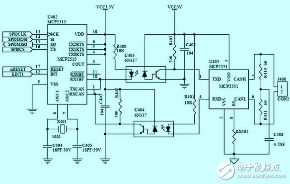
The SPI interface of the S3C2410 is compatible with the SPI V2.11 protocol and supports three data transfer modes: query, interrupt and DMA. The MCP2515 is connected to the SPI0 port of the S3C2410. The interconnection relationship is shown in Figure 1.

Figure 1 PROFIBUS network characteristics
(1) This interface design does not use 5 pins such as TXnRTS and RXnBF, and uses the total interrupt pin INT. Therefore, the corresponding function pins of the transmit request and receive completion interrupts are not enabled during software design, and in this design. This pin is also used for other purposes. After responding to the total interrupt, the processor accesses the corresponding internal register of the MCP2515 through the SPI interface to determine the specific interrupt event and process it.
(2) In order to isolate the interference signal on the bus and improve the reliability of the system, a light separation is adopted between the CAN controller and the CAN transceiver. The two sides of the light barrier should be powered by separate power supplies and should not be directly connected to other parts of the system.
(3) Two equivalent resistors (R410, R411) and bypass capacitors (C408) are used between CANH and CANL to improve the EME (Electro MagnaTIc Emission) performance and reduce the interference of this part to other parts of the system.
(4) The OST (Oscillation Start Timer) remains in the reset state during the initial 128 OSC clock cycle of the MCP2515 after initial power-on, reset, and wake-up from Sleep mode. It should be noted that the SPI should not be operated before the OST times out.
(5) RX is designed to reduce EMI (Electro MagnaTIc Interference). The conversion rate of CANH and CANL is proportional to the current flowing through RX.
Shanghai Janetec Electric Co., Ltd. , https://www.janetecelectric.com