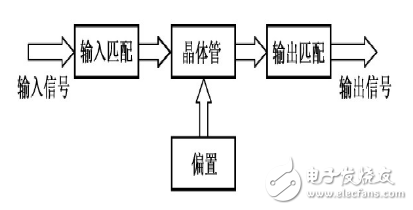
RF power amplifiers (RF PAs) are an important part of a variety of wireless transmitters. In the pre-stage circuit of the transmitter, the RF signal generated by the modulating oscillating circuit has a small power, and needs to pass through a series of amplification-buffering stage, intermediate amplification stage, and final stage power amplification stage, and after obtaining sufficient RF power, it can feed Radiate out onto the antenna. In order to obtain a sufficiently large RF output power, an RF power amplifier must be used.
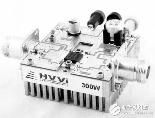
At present, power amplification can be realized by a power amplifier chip, but the core is a triode and a field effect transistor.
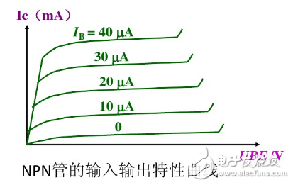
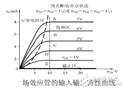
Based on the RF amplifier, the core part is usually composed of a triode and a FET or a MOS tube. I believe that everyone is no stranger. Its input and output relationships are shown in the figure.
Unlike other Class A, Class B, and Class C RF power amplifiers, RF power amplifiers do not require high voltages; unlike other low frequency power amplifiers, there is not much bandwidth. The field effect transistor of the D-type amplifier works in the switching state, and the drain dissipation power is very low. Although the on-off and off-period work is very powerful in the linear region, the operating frequency is high, the transition period is very short, and the working efficiency is higher than that of the conventional power amplifier. Greatly improved, in fact, it can be more than 90%.
The FET D-type amplifiers are composed of two or more pairs of tubes, which are divided into two groups of turns to conduct power amplification tasks. The excitation voltage that controls the FET to operate in the switching state may be a sine wave or a square wave. There are two kinds of actual circuits, namely current switch type and voltage switch type. Because the current is a square wave in the current switching circuit, the switching time of the FET switch cannot be ignored when the operating frequency is high, so the voltage switching circuit is used in the medium wave broadcast transmitter. It is divided into two modes: full bridge and half bridge.
The bridge power amplifier is the RF power amplifier in the medium wave broadcast transmitter that is currently produced and operated. The bridge power amplifier is connected by four FETs in the form of bridges. The connection method of working in the D-type switch amplification mode is called bridge type. Power amplifier, this full bridge connection is an H-type, so it is also known as H-type D-type amplifier. The full-bridge circuit is composed of two half-bridges. The output of the left and right parts is connected to the opposite ends of the composite transformer primary coil. This structure is similar to the traditional push-pull circuit. The two RF power amplifiers are designed to be powered by separate power systems. The push signals are also independently input by the two bridges. The half-bridge operation of the RF power amplifier is utilized in the pre-driver stage.
Dc Gear Motor,Dc Motor 24V,220V Gear Motor,Permanent Magnet Dc Motor
NingBo BeiLun HengFeng Electromotor Manufacture Co.,Ltd. , https://www.hengfengmotor.com