Optocouplers are an indispensable device in the design of electronic circuits, which can convert light energy and electrical energy to each other, so as to achieve the purpose of free control of electrical energy. And with the diversification of modern power supply equipment, the application of optocouplers is becoming more and more extensive. In the following content, Xiaobian will introduce some common sense of optocoupler in daily design, let's take a look.
1. There are many types and types of optocouplers. In practical applications, different types of optocouplers should be selected according to different circuits. For example, the input part has two "back-to-back" LED optocouplers, suitable for AC input; optocoupler with Darlington output structure, suitable for applications where large current is output; output is triggered by light An optocoupler consisting of a triac is suitable for driving an AC load.
2. The package form of the optocoupler is completely different from the internal structure and circuit function. Optocouplers with the same shape may have completely different functions; circuits with the same function may also be used in different packages. Therefore, when choosing or replacing the optocoupler, it can only be based on its model. In addition, when the optocoupler is directly used to isolate the transmission analog quantity, its output nonlinearity must be considered. When it comes to isolating the transmission of digital quantities, consider its response speed problem. If there is a power requirement for the output, the power interface design problem must also be considered.
3. Photocouplers In terms of output characteristics, there are two types of nonlinear (digital) optocouplers and linear (analog) optocouplers. The current transfer characteristic of nonlinear optocouplers is non-linear. These products are suitable for the transmission of switching signals and are not suitable for transmitting analog quantities. The current transmission characteristic curve of the linear optocoupler is close to a straight line, and the performance is good when the signal is small, and the isolation can be controlled by the linear characteristic. Photoelectric couplers commonly used in switching power supplies such as color TVs and monitors are linear products. If they are replaced with non-linear products, it is possible to make the oscillation waveform worse. In severe cases, parasitic oscillations occur, causing interference to image images and the like. The load capacity is reduced. Therefore, when repairing the switching power supply of home appliances, if the photocoupler is found to be damaged, it must be remembered to replace it with a linear photocoupler.
Commonly used 4-pin linear optocouplers are PC817A~C, PC111, TLP521, etc. The 6-pin linear optocouplers include LP632, TLP532, PC614, PC714, PS2031 and so on. 4N×× series (such as 4N25, 4N26, 4N35, 4N36, etc.) optocouplers, which are very familiar to electronic enthusiasts, are mainly used to transmit digital signals (high and low levels). They are nonlinear optocouplers with poor linearity. Is not suitable for use in switching power supplies.
4. The establishment of the "isolation" function of the optocoupler needs to meet certain external conditions: First, the input power and the output part of the optocoupler must be independent power sources respectively. If one end shares a power supply, the optocoupler is isolated. The effect will be meaningless; secondly, when optocouplers are used to isolate the input and output channels, all signals (including digital signals, control signals, and status signals) must be isolated so that there is no electrical isolation on either side. The connection, otherwise this isolation is meaningless.
5. The input pins of the optocoupler are designed on one side of the package, while the output pins are packaged on the opposite side. This structure can ensure the insulation resistance between the front and rear stages is as high as 109~1013 ohms, and it is beneficial to increase the maximum possible value of the isolation voltage, which is convenient for the installation of the circuit. However, in a multi-channel optocoupler, although the isolation voltage between each input and output is high (generally ≥ 1.5kV), the potential difference between adjacent channels is never allowed to exceed 500V. In addition, the input source of the optocoupler is mostly an infrared light-emitting diode, and its reverse breakdown voltage is generally low, and some are only 3V. In use, it must be noted that the input end cannot be reversed. In order to prevent the infrared light-emitting diode from breakdown due to excessive back pressure, a protection diode can be connected in reverse parallel at its input.
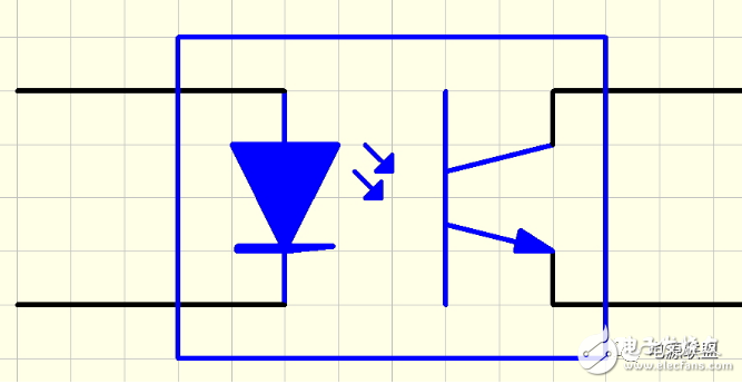
6. Usually, single-channel phototransistor optocouplers are mostly sealed in a 6-pin package. The base of the phototransistor is led out of the package for use. In normal use, the base is not open. If the base pin is shorted to the emitter pin, the phototransistor can be converted into a photodiode. In this case, although the current transfer ratio of the photocoupler is lowered, the response time can be increased.
7. In the amateur electronics production or appliance repair, if you can not find a suitable optocoupler at hand, take a 3mm high-brightness LED and a 2mm 3DU silicon phototransistor, and use electrical insulation black rubber cloth to make them The light-emitting surface and the light-receiving surface were rolled up, and then placed in a black hard plastic tube of about 6 mm × 20 mm, and the both ends were sealed with black epoxy resin. It should be pointed out that when selecting LEDs and phototransistors, the spectral characteristics (especially the peak wavelength) of the two must be kept as consistent as possible, otherwise the effect of the optocoupler will be affected. The phototransistor may also be a photosensitive device such as a photodiode or a photoresistor as needed. The cost of this self-made optocoupler is less than 2 yuan, and the main characteristic parameters can refer to the characteristics of the two tubes selected.
8. The common optocoupler is to package the light-emitting device and the photo-sensitive device oppositely, belonging to the internal optical path optocoupler, and can be used for coupling and transmitting electrical signals. The optocouplers described above belong to the internal optical path optocoupler.
In addition, there is a type of light sensor (also called photoelectric switch or photoelectric intermittent detector) that is used to measure the presence, the number and the moving distance of an object. It is divided into a shading type (optical type) and reflective. Two types of light (reflective type), because such light sensors also have optical coupling characteristics, and its optical path is outside the device, so these devices are collectively referred to as external optical path optocouplers.
The input end and the output end of the external optical path optocoupler are also mostly isolated from each other, that is, the light emitting device and the photosensitive device are independent of each other and maintain electrical insulation. However, some products are non-isolated, that is, the light-emitting device and the photosensitive device are common ground. The external optical path optocoupler has the disadvantage that it is easily interfered by external light, especially when it is used under strong ambient light, and its detection function may be lost.
9. Welding ordinary optocouplers generally use a low-power electric iron of about 20W. The soldering iron tip is preferably formed into a narrow bevel to ensure accurate solder joint position. The soldering time should not be too long to prevent the device itself or the board from being burnt.
The above is some points of use that the optocoupler needs to pay attention to during daily design and use, or it is easy to be ignored. For newcomers to the power supply, it may take a few minutes to read this article before using it in formal contact with the optocoupler design . I believe it will play a big role in the learning. If the reader has a certain foundation, then this article will be a relatively good material article.
90degree Hybrid Coupler, up to 40GHz, connector SMA,N,2 92mm are avaliable. Customized frequency and optimized specifications available,contact us with your requirement.
Rf Hybrid Coupler,90 Hybrid Coupler,90 Degree Hybrid Coupler,20Db Directional Coupler
Chengdu Zysen Technology Co., Ltd. , https://www.zysenmw.com